Inner secrets of Synology Hybrid RAID (SHR) – Part 2

Changing the first disk and my case to Synology support

Now it was time to replace the first disk. As I assumed this would never go wrong (!) and did not plan to document the upgrade, I did not take out any information about the partitions, mdraids and volumes during this first disk swap.

The instructions from Synology are quite good for this (until something breaks down):
Replace Drives to Expand Storage Capacity

Basically it says: replace the disks one by one, start with the smallest and wait until completion before replacing the next.

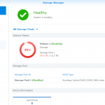
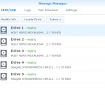
For the first disk swap, I actually shut down my DS1517 before replacing the disk (many models, including DS1517, supports hot swapping the disks). When the disk was replaced and I powered up the DS1517, and as expected I got the “RAID degraded” beep.
Did a check that the new drive was recognized, and then started the repair of the storage pool. As this will usually take many hours, and this was done in the evening, I have no idea of the actual time spent for repairing (rebuilding) the pool. This was about 90% finished when I stopped looking at the status around midnight that day.

The next day, I see that it had “restarted” (lower percentage than yesterday), but this is actually the next step that is initiated directly after repairing the pool. It’s called “reshaping” and during that process other mdraids are changed and adjusted (if possible) against the new disk.

Changes during the first disk swap

These are only assumptions, because I did not take enough info in between swapping the disk and until about a third into reshaping.

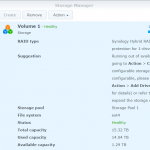
At the point of changing the first disk (refer to the previous part of my article), my storage pool/volume consisted of two mdraids joined together:
md2: RAID 5 of sda5, sdb5, sdc5, sdd5, sde5: total size about 11.7TB
md3: RAID 1 of sdd6, sde6: total size of about 4.8TB

When I pulled the first drive (3TB) and replaced it with a 14TB drive, I assume the partition table on that disk was created like this (status pulled from the mid of reshaping after first disk swap, so I’m pretty sure this is correct):

/dev/sda1                  2048         4982527         4980480  fd
/dev/sda2               4982528         9176831         4194304  fd
/dev/sda5               9453280      5860326239      5850872960  fd
/dev/sda6            5860342336     15627846239      9767503904  fd

sda5 was matched up with the size of the old sda5 (and the ‘5’-partitions on the other disks)
sda6 was also created in either the step before rebuild, or right before reshaping (this partition match the size with the ‘6’-partitions on sdd and sde.
Because the (14T) disk is larger than the previous largest (8TB) one, there are some non-partitioned wasted space (about 5.8TB which will come into use after the next disk swap).

Reshaping

Again, I have not taken any full status dumps so that my information can be confirmed, but this is what I see afterwards, and adding my guesses to it because of the better logging of later disk swaps.

After the storage pool was repaired, reshaping started automatically. During this step, the RAID1 consisting of sdd6 and sde6 (md3) were changed into RAID5 consisting of sda6, sdd6 and sde6.

At about 30% into the reshaping phase, my NAS went unresponsive (disconnected both shell and GUI), and I had to wait all day until I came home and did a hard reset on it and hoped everything went well..

In the meantime, I logged a case to the Synology support (see “Part 2b” of this article). They were not of any direct help, and the hard reset did take the NAS back to continuing the reshaping process.

Inner secrets of Synology Hybrid RAID (SHR) – Part 1

Inner workings of Synology Hybrid RAID

Maybe a too much promising title for this post, but this is my guesswork on how SHR works when replacing drives. If anyone have a spare DS1517 (or later device, with at least 4 slots) to donate, I will investigate this further, cannot afford to do it on my primary NAS because of risk of loosing data – and now even not possible without upgrading the disks again to larger ones).

I will also post here my case (more or less in full) sent to Synology when the NAS got unresponsive (crashed) during the rebuild/reshaping process.

What is Synology Hyrbrid RAID ?

This is in fact the only thing Synology themselves have briefly explained in their documentation:
What is Synology Hybrid RAID (SHR)

My short explanation is that it is a software RAID that is able to maximize the utilization of mixed sized hard drives. For simplicity, Synology illustrates this with drives varying of 500GB to 2TB (in 500GB increments), possibly fooling some people to think that the disks are always split into 500GB partitions.

My findings while expanding my DS1517 (from 3TB, 3TB, 3TB, 8TB, 8TB to all 14TB) is that the remaining space of the drives are splitted in as few parts as possible to obtain the maximum available space (after setting aside about 2.5GB for the DSM (operating system) and 2GB for swap).

Replacing disks and rebuilding the RAID

Before I replaced the first disk, I actually forgot to view and save down the info about the partitions, mdraid volumes and logical volumes (I might have that somewhere else, but I will not look for it now). Based on how it looked after the first disk had been replaced, and the rebuild was done (in the process of reshaping) it should have been something like this:

# sfdisk -l
/dev/sda1                  2048         4982527         4980480  83
/dev/sda2               4982528         9176831         4194304  82
/dev/sda5               9453280      5860326239      5850872960  fd

/dev/sdb1                  2048         4982527         4980480  83
/dev/sdb2               4982528         9176831         4194304  82
/dev/sdb5               9453280      5860326239      5850872960  fd

/dev/sdc1                  2048         4982527         4980480  83
/dev/sdc2               4982528         9176831         4194304  82
/dev/sdc5               9453280      5860326239      5850872960  fd

/dev/sdd1                  2048         4982527         4980480  fd
/dev/sdd2               4982528         9176831         4194304  fd
/dev/sdd5               9453280      5860326239      5850872960  fd
/dev/sdd6            5860342336     15627846239      9767503904  fd

/dev/sde1                  2048         4982527         4980480  fd
/dev/sde2               4982528         9176831         4194304  fd
/dev/sde5               9453280      5860326239      5850872960  fd
/dev/sde6            5860342336     15627846239      9767503904  fd

Note: The partition types for sd[a-c][1-2] seems incorrect as these where changed to “fd” later on during the process, or it might have been something changed by Synology on later DSM versions (but not at the point of updating DSM).

Partitions 1-2 are the system and swap partitions on all the drives, sized 2.5GB respectively 2GB.
Partition 5 is a part of the storage space available in the volume on the NAS. In this case it is about 2.9TB in size (the maximum available on the smallest disks).
Partition 6 is the second part of the total storage space. At this time those partitions are about 4.8TB in size.

mdraid volumes

Out of the partitions above, the Synology creates these mdraid volumes:
md0: RAID 1 of sda1, sdb1, sdc1, sdd1, sde1: total size 2.5GB used for DSM
md1: RAID 1 of sda1, sdb2, sdc2, sdd2, sde2: total size 2GB used for swap
md2: RAID 5 of sda5, sdb5, sdc5, sdd5, sde5: total size about 11.7TB
md3: RAID 1 of sdd6, sde6: total size of about 4.8TB

LVM logical disk

md2 and md3 are joined together into a logical disk using LVM, which gives about 16.5TB space in total for the storage volume on the NAS (Synology DSM says 15.5TB, but the difference is only because of how I estimate the space and how Synology does – I just take the block count, divide by two, then use a one decimal precision – which is adequate enough for this description).

DSM Storage Manager before replacing the first disk

… to be continued in part 2 …

Email relaying – smarthost setup

Overview of alternatives for relaying emails

Free SMTP Servers for Sending Emails – 2021
Free SMTP Servers & Free SMTP Relay Services

Relaying emails using a Gmail account

https://support.google.com/a/answer/2956491?hl=en

Main disadvantages:

  • Low daily (24hr rolling) limit of 500 messages
  • Sends as (and takes replies on) the gmail account used for relaying

All limitations: https://support.google.com/a/answer/166852?hl=en

Setup guide for UNIX-like OSes (msmtp / msmtp-mta)

msmtp/msmtp-mta is a lightweight solution for relaying mail through gmail or any other external service.
I have successfully followed this guide:
Using MSMTP with Google SMTP Relay on Ubuntu 20.04 (DFT blog)
Another guide:
Use external SMTP server for system mails on Linux
See also:
msmtp documentation (Arch Linux Wiki)

Setup guide for multiple UNIX-ish OSes (for Postfix)

https://www.howtoforge.com/tutorial/configure-postfix-to-use-gmail-as-a-mail-relay/

Quick setup (Ubuntu and other):

Gmail account: allow insecure apps
https://myaccount.google.com/security?gar=1

Required software: postfix and mailutils

/etc/postfix/sasl_passwd:

[smtp.gmail.com]:587    username@gmail.com:password

Protect and process password file:

chmod 600 /etc/postfix/sasl_passwd
postmap /etc/postfix/sasl_passwd

Configure postfix:
/etc/postfix/main.cf:

relayhost = [smtp.gmail.com]:587
smtp_use_tls = yes
smtp_sasl_auth_enable = yes
smtp_sasl_security_options =
smtp_sasl_password_maps = hash:/etc/postfix/sasl_passwd
smtp_tls_CAfile = /etc/ssl/certs/ca-certificates.crt

Restart Postfix

systemctl restart postfix.service

or

postfix stop
postfix start

WP plugin for setting sender name (address can not be changed): CB Mail Sender

Relaying emails using Elastic-Email

Elastic-Email is primarily a email marketing system like MailChimp, but can also act as a SMTP relay.

Main advantages:

  • Domains and email address can be confgured as approved senders, email will be sent using one of the confirmed senders
  • API available

Main disadvantages

  • Impossible to get rid of the “unsubscribe” link in every email sent
  • Tracking portions are added to links, and links are destroyed (no longer clickable) in the sent emails

Setup guide

https://help.elasticemail.com/en/articles/2388043-how-to-configure-postfix-with-elastic-email

WP plugin: Elastic Email Sender

Relaying through Oracle Cloud

https://docs.cloud.oracle.com/en-us/iaas/Content/Email/Concepts/overview.htm

Relaying mail from WordPress

The system-wide configurations and alternatives above work well for WordPress too, but you might want to finetune some settings for the emails being sent from WP. That includes the sender name, reply-to email, or you might even want to send these with another email account (or email relay service).
I found the plugin “Post SMTP Mailer/Email Log” (Post SMTP / PostmanSMTP) be the best suitable for this (there are many others available, so this might NOT be the best for everyone):

Simple four-way kickstart switch with M27C160

This post has been cloned from http://blog.system11.org/?p=2666
Originally written 15 Dec 2017
Some links and inline-notes, both displayed in red, has been added to this guide after cloning.

Amiga (various models) Kickstart switcher

The Amiga has had multiple firmware versions over the years, known as “Kickstart”. Unfortunately a lot of software that hits the hardware directly is affected by which version of Kickstart you’re using, leading to various hardware and software solutions.

The software ones (for example Relokick) do work, but if you have enough boot time toggles it can start getting unwieldy managing which things are resetting and why – for example booting into 68000 mode on your accelerator card, then booting Relokick to drop to Kickstart 1.3 which involves another reset. Hardware options are definitely the way to go.

There are some quite complex ones which allow you to switch on reset with keyboard strokes, but I found one main problem with these – they’re always out of stock. Additionally they only allow you to switch between two ROMs and have quite large physical footprints because for some reason people are really “purist” over Kickstart ROMs, copyright and so on meaning multiple chips or insane solutions like having to download original chips into onboard flash.

As many reading will know, I’m a member of The Dumping Union, so I don’t much care. So I made a small quad switcher board which anyone can make without having to worry about stock availability. It won’t work in all machines, if yours can cope with single 20 pin chips then you’ll be fine. This is revision 1.1, the 1.0 included a mistake which affected the logical workings of the jumpers.

So what we have is a 27C160 (16mbit) chip split into four areas by the jumpers toggling high address lines on the chip, presented to the motherboard as a standard 27C400. If you want to make life easier when you’re building this, solder the middle pin strip first, then the resistors, socket, other strip and header in that order. It should look a bit like this:

And it installs like this (photo taken in Rev 6 A2000):

As with my drive switcher project, I suggest you get the boards made by OHS Park, here’s a handy ordering link:
Order from OSH Park

However if you want to manufacture them yourself or make changes, here’s the Eagle CAD file:
A2000_ks_quad_11

Parts list:

1x 27C160 EEPROM
2x 20 way male pin strip, turned pin type
2x 4.7k ohm resistor 1/2 watt
1x 4 pin right angle pin header
1x 42 pin DIL socket
2x jumpers, switches, or 2P4T rotary switch (examples)

To make the image for this chip just get your four chosen ROM images, double the size of any 2mbit (256k) images and copy the lower half into the upper half, and then compile them into a single 16mbit image. There are loads of ways of doing this, I just used a Linux command line:

$ cat KICK13.ROM > quadbios.bin
$ cat kickstart2_04.rom >> quadbios.bin
$ cat Kickstart3.1.rom >> quadbios.bin
$ cat DiagROM >> quadbios.bin

As you can see I chose 1.3, 2.0, 3.1 and the awesome Amiga Diagnostic ROM (http://www.diagrom.com), once you have that image you will need to byte swap it if you’re using images used by emulators, but not if you’re using genuine chip dumps. As a sanity check when you load the file into your programmer software to burn the 27C160, look at the buffer – if you see readable headers instead of slightly scrambled ones, you’ll need to byte swap it. In fact it’s probably best to check the individual ROMs you plan to use before joining them together, that will work just as well.

As for how to actually use it – well that’s up to you. If you ground the second pin of J1 or J2 you’ll change which segment of the 27C160 is being accessed according to this table:

J1  J2
ON  ON  = ROM 1
OFF ON  = ROM 2
ON  OFF = ROM 3
OFF OFF = ROM 4

If you do this while the machine is running it will tend to crash horribly – but switching it during a reset seems to work, or by turning it off first. You could attach 2 toggle switches to it, or do as I have and wire up a 2 pole 4 throw switch – if wired correctly this will let you choose any of the 4 possible combinations. I used one of these:

So if you look at the above pinout, I connected J1-1 to A, J1-2 to 1 & 3, J2-1 to B, and J2-2 to 5 & 6.

You may not make these to sell unless you are charging a minimal amount for assembly and parts. Everything else is fine.

Amiga Forever by Cloanto

The purpose of this article is to document some parts of the pre-configured Amiga systems in Amiga Forever. Probably the most of the details given here can also be found in the documentation at amigaforever.com

Default folder and file locations

Kickstart and other ROMs:
C:\Users\Public\Documents\Amiga Files\Shared\rom

“Built-in Boot” when set to any of the floppy disk images:
C:\Users\Public\Documents\Amiga Files\Shared\adf

“Built-in Boot” when set to any of the hard disk images:
C:\Users\Public\Documents\Amiga Files\Shared\hdf

“Built-in Shared” when set to “Local folder”:
C:\Users\Public\Documents\Amiga Files\Shared\Workbench

When listed as “Shared\dir\something”:
C:\Users\Public\Documents\Amiga Files\Shared\dir

Pre-configured Amiga systems

Amiga 1000

Model: Amiga 1000
ROM: Amiga 1.1 (NTSC)
CPU: 68000
RAM: 256k CHIP
Media: Built-in Boot: Workbench 1.0 (floppy disk image)

Amiga 2000

Model: Amiga 2000
ROM: Amiga 1.3
CPU: 68000
RAM: 512k CHIP + 512k SLOW
Media: Built-in Boot: Workbench 1.34 (floppy disk image)

Amiga 500

Model: Amiga 500
ROM: Amiga 1.2
CPU: 68000
RAM: 512k CHIP
Media: Built-in Boot: Workbench 1.34 (floppy disk image)

Amiga 3000

Model: Amiga 3000
ROM: Amiga 3.1
CPU: 68030, 68882
RAM: 1MB CHIP + 1MB FAST
Media: Built-in Boot: Workbench 3.11 (hard disk image)

Amiga 500 Plus

Model: Amiga 500 Plus
ROM: Amiga 2.04
CPU: 68000
RAM: 1MB CHIP
Media: Built-in Boot: Workbench 2.04 (floppy disk image)

CDTV

Model: CDTV
ROM: Amiga 1.3
CPU: 68000
RAM: 1MB CHIP
Media: None

Amiga 1200

Model: Amiga 1200
ROM: Amiga 3.1
CPU: 68EC020
RAM: 2MB CHIP
Media: Built-in Boot: Workbench 3.1 (floppy disk image)

Amiga 4000

Model: Amiga 4000
ROM: Amiga 3.1
CPU: 68040
RAM: 2MB CHIP + 4MB FAST
Media: Built-in Boot: Workbench 3.11 (hard disk image)

Amiga 600

Model: Amiga 600
ROM: Amiga 2.05
CPU: 68000
RAM: 1MB CHIP
Media: Built-in Boot: Workbench 2.04 (Floppy disk image)

Amiga CD32

Model: CD32
ROM: Amiga 3.1
CPU: 68EC020
RAM: 2MB CHIP
Media: None

Walker Prototype

Model: Walker
ROM: Amiga 3.2 (beta)
CPU: 68030, 68882
RAM: 2MB CHIP, 4MB FAST
Media: Shared\dir: Walker-System
Media: Shared\dir: Walker-Work

Amiga 4000 PPC

Model: Amiga 4000
ROM: Amiga 3.1
CPU: 68040
RAM: 2MB CHIP + 256MB Z3 + 128MB PPC
PPC: CyberStorm (exclusive mode)
SCSI: CyberStorm PPC
Video: RTG (Picasso IV)
Media: Built-in Shared: Local folder
Media: Deploy a-750mb.hdf

Workbench 1.3

Model: Amiga 2000
ROM: Amiga 1.3
CPU: 68000
RAM: 512k CHIP + 2MB FAST + 512k SLOW
Media: Built-in Boot: Workbench 1.35 (hard disk image)
Media: Built-in Shared: Local folder

Workbench 3.x

Model: Amiga 4XXX
ROM: Amiga 3.X
CPU: 68020, 68882
RAM: 2MB CHIP + 64MB Z3
Video: RTG (synthetic), 16MB
Media: Built-in Boot: Workbench 3.X (shared directory)
Media: Built-in Shared: Local folder
Media: Shared\dir: Work

AmigaSYS

Model: Amiga 4XXX
ROM: Amiga 3.X
CPU: 68020, 68882
RAM: 2MB CHIP + 64MB Z3
Video: RTG (synthetic), 16MB
Media: Shared\hdf AmigaSYS4.hdf
Media: Shared\dir AmigaSYS4-Work
Media: Shared\dir

AROS

Model: AROS
ROM: AROS Latest
CPU: 68020, 68882
RAM: 2MB CHIP, 64MB Z3
Video: RTG (synthetic), 16MB
Media: Shared\dir AROS

Some resources:

ROM and Operating System Files in Amiga Forever
Classic Support Media
Amiga Forever 3.X ROM Improvements
Amiga Forever Workbench 3.1 Improvements
Amiga Forever Workbench 3.1 Duplication Instructions
Amiga Model-Specific ROM Differences

Burning Kickstart ROMs for the Amiga

(cloned from https://www.software-by-mabe.com/blog?3&catid=2)
Links and inline-notes, both displayed in red, has been added to this guide after cloning.
See also:
Burn Damn ROM Burn

Burning your own Amiga ROMs (EPROMs)

01/26/2019 | Amiga | Amiga ROM AmigaOS

With the release of the latest AmigaOS version (3.1.4) the package you could buy included ROM images to be used for either maprom (depending on your accelerator card tool support) or for burning it to a ROM.

Maprom is probably preferred, because it’s more flexible, but not always possible. For instance the A3440 card can’t do maprom. Or if you have no accelerator at all you can’t do maprom either.

Which leaves only a few options. Either you can buy the ROM, have someone burn it or burn it yourself.

Here I want to show how it works to burn it yourself.

What you need:

– an EPROM programmer. I have chosen the low cost GQ-4×4 USB programmer.

– to program the EPROMs used in an Amiga you have to get a 16-Bit 40/42 pin ZIF adapter board for the burner:
ADP-054 16 Bit EPROM 40/42 pin ZIF adapter

– an UV eraser, which can erase the EPROMs, in case something goes wrong.

– then you need EPROMs. The types used in A500/A600/A2000 are 27C400. I found the following to work which can be ordered in eBay: AMD27C400

– for burning ROMs for A1200/A4000 you need 27C800 / AMD27C800 roms, two of them to burn one ROM.

– and certainly a ROM image you want to burn.

Sometimes there are good offers at Amazon or eBay for a complete package (except the EPROMs).
You shouldn’t pay more than €150 for the GQ-4×4, the adapter board and the eraser.
(https://www.amazon.co.uk/gp/product/B011HVON3A/)

Here is a picture of the device with attached adapter board with an EPROM inside.
GQ programmer with adapter board and EPROM

Then you need to download the software for the burner. That is a) the burner software itself named “GQUSBprg”. The latest version as of this writing is 7.21.
And you need the USB driver 3.0.

Can be downloaded here: http://mcumall.com/store/device.html

When you connected the burner and installed the software we can start.
Now open the burner software. Make sure that there is no EPROM put in.

1. first step is to select the device, or the EPROM to burn.

Make sure you choose either AM27C400 or 27C400.

2. Next we’ll make a voltage check to see if the burner has all voltages in order to properly burn the EPROM.

I found that while you can attached a power supply on the burner it is not required. The USB provides enough power.

3. Load the ROM image into the buffer.

When you load the image make sure you choose .bin (binary).

!!! This is important, or otherwise the programmed ROM won’t work.
After you loaded the ROM image, you have to make sure to swap bytes.
This can be done in the ‘Command’ menu of the software.
Check first by selecting the “Buffer” tab. If you find some readable text in the beginning of the buffer, you need to byteswap it.

4. Now you have to put in your EPROM into the ZIF slot.

Make sure it sits tight and doesn’t move anymore.

5. Make a blank check to see if the EPROM is empty.

6. When the EPROM is blank we can write it.

When the write process is finished it’s done.

You can take out the EPROM and put it into the Amiga and it should work.

Some notes:
Partly this whole process of writing the ROM was a real pain because the GQ burner would just stop writing at some address. And in fact I had to get the package replaced including the adapter board.

I had first tried it in a virtual machine (VMware Fusion on Mac) but this doesn’t work for some reason as the GQ programmer detaches and re-attaches to the USB bus on some of the operations and that doesn’t seem to be working reliably in a VM.

Commenting on my own post:

The Amiga 4000 can only use 512k EPROMs, hence only 27C400 will work.
The Amiga 1200 can also use 27C800 (1MB).

The byte-swap, if your ROM image is already byte-swapped, then you don’t need to do this here.
Some ROM images, which are ready to burn have this already.
However, if you want to burn ROM images that are used in maprom or UAE, then you have to byte-swap.

07/15/2019 | Manfred |


Problems writing or verifying ROMs ?

If you get messages like Write failed, Address=0x000200, Buffer=0x40 Device=0x00 (or any other address or values), or if the verification fails after the ROM was written, you can try a few thing to remedy the problem:
* With the level on the ZIF for the ADP-054 adapter down, gently wiggle the adapter board up/down (on each of the pin rows) while holding it down so it doesn’t pop out.
* While inserting the EPROM in the adapter, hold the chip down and pull it towards you.
* Try another profile for the chip you are using. Usually, you should try the best match first, then go for the alternatives. If your ROMs are AM27C400, you can also try the M27C400 and 27C400 profiles (when I checked, the profiles were similar, the only difference beside their names was that the AM profile had voltage settings)
* Try decreasing the write speed from the default (+2) to 0 (zero).

Print a support bracket for the adapter

If you have a 3D-printer or have access to one, this support for the adapter is helpful in making the adapter not wiggling on the ZIF-socket, especially when inserting EPROMs in the outer sockets on the adapter.


https://www.printables.com/model/317538-gq-4×4-usb-programmer-adp-054-adapter-support-brac/files

Resources

Making a custom kickstart 3.9 ROM
Guide: Create and Burn a custom Kickstart 3.9
AmigaOS 3.9 Kickstart and Patches Guide
Classic Amiga Wiki – Kickstart 3.9
Help making Custom Kickstart rom
EEPROM on A1200?
Making a custom kickstart 3.1.4 ROM
Remus and ROMsplit to create your own 3.1.4 KS
Amiga 2000 1MB ROM Upgrade (and other things) – Part 3 (Amiga Retro)


Quick Tutorial – Making a Workbench 3.1.4 ROM (deleted)
https://www.youtube.com/watch?v=FfkGgCiu8sc

Willem EPROM programmer
GQ-4X User’s Manual
Software and USB-driver download
27C400 EPROMs (for A500/A600/A2000 and A4000 ?)
27C800 EPROMs (for A1200 only ?)